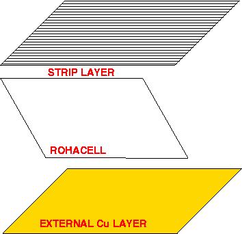
Structure
|
1a.
|
Cathodes elements
|
1b.
|
Strip layer layout
|
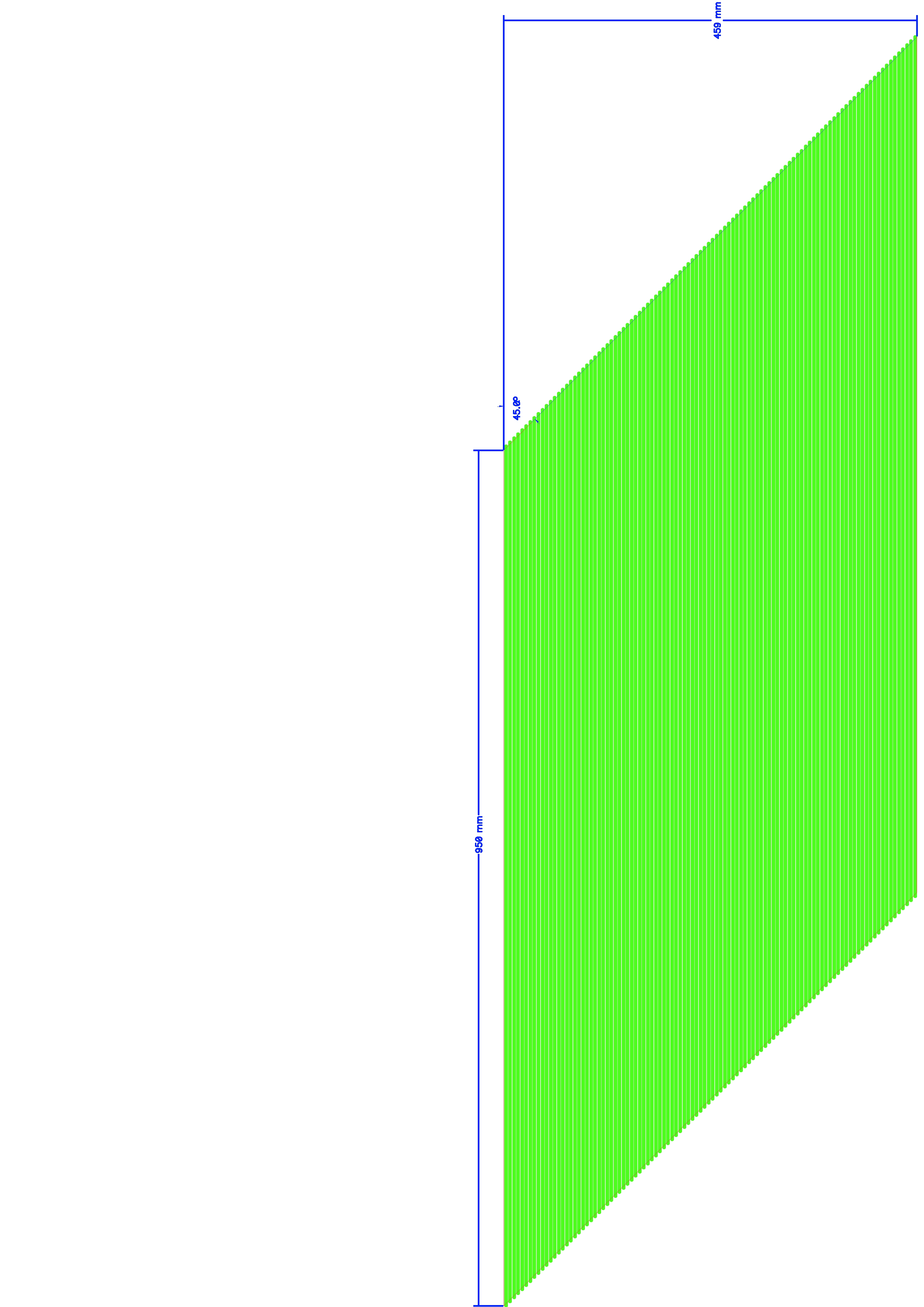
1c.
|
Rohacell sheet
|
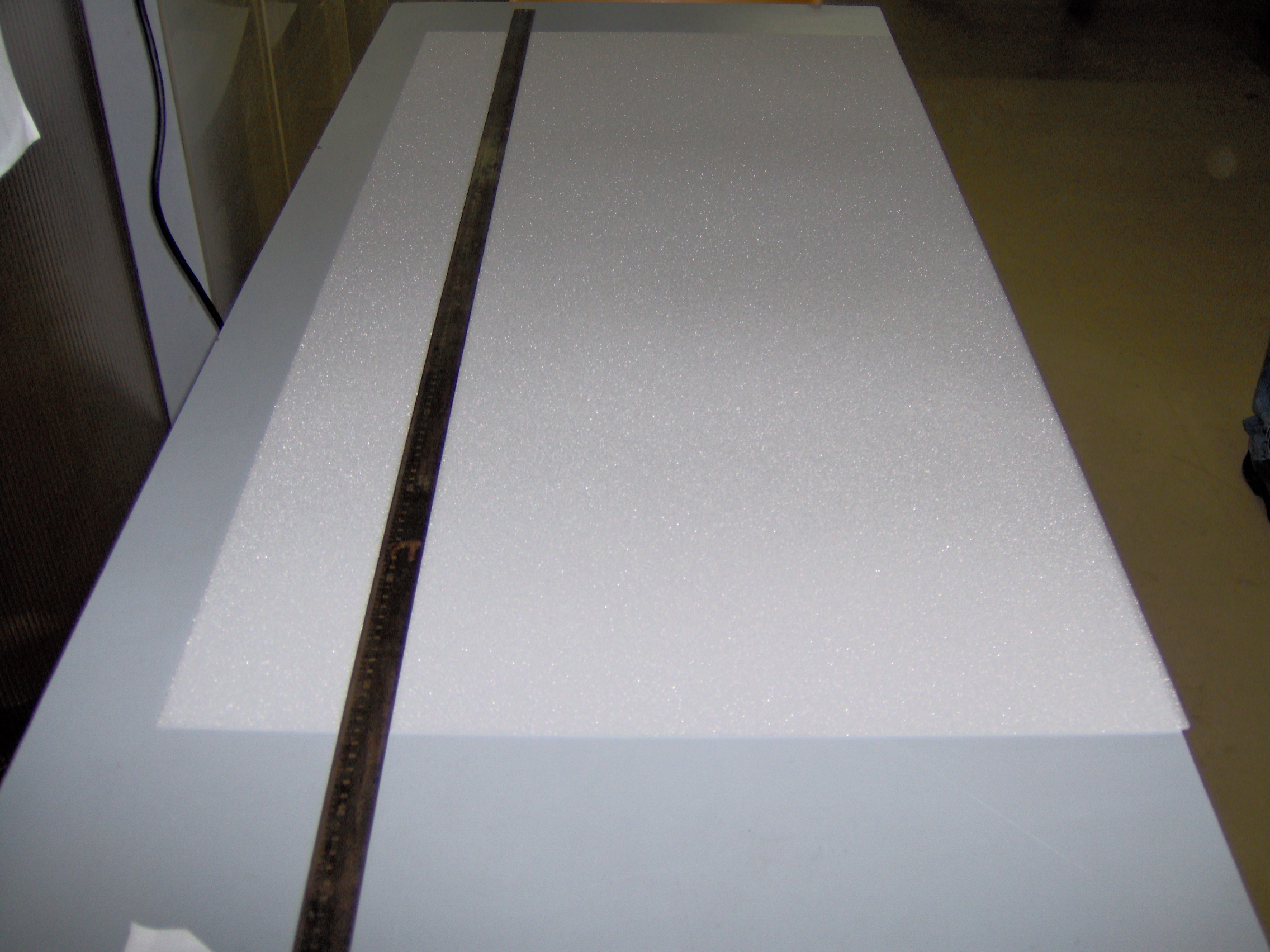
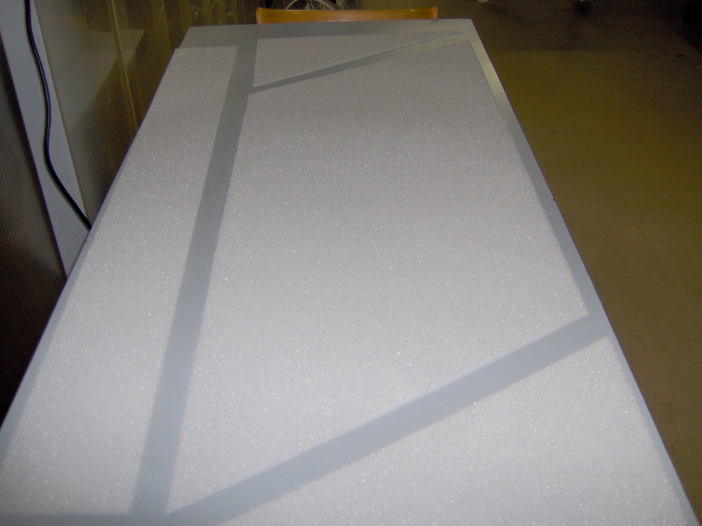
2.
|
Rohacell sheet
|
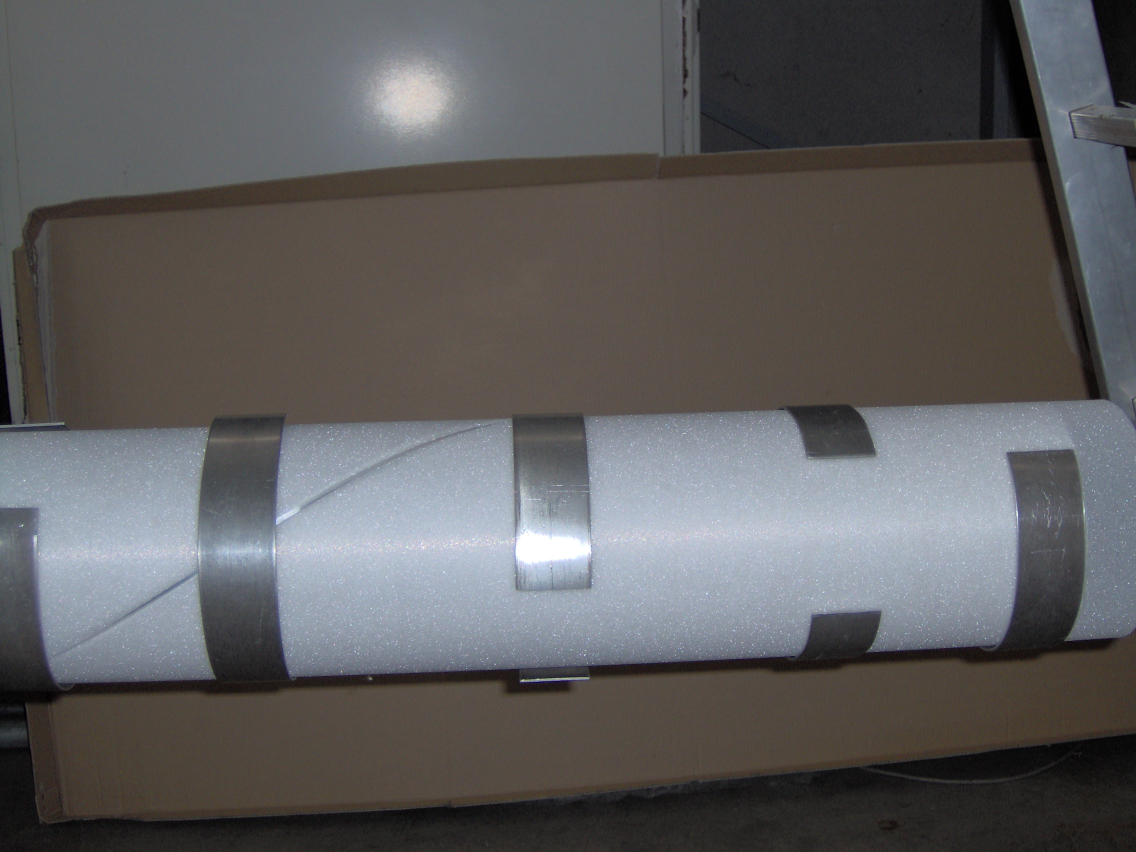
3.
|
Rohacell wrapped and fixed to
mandrel
|
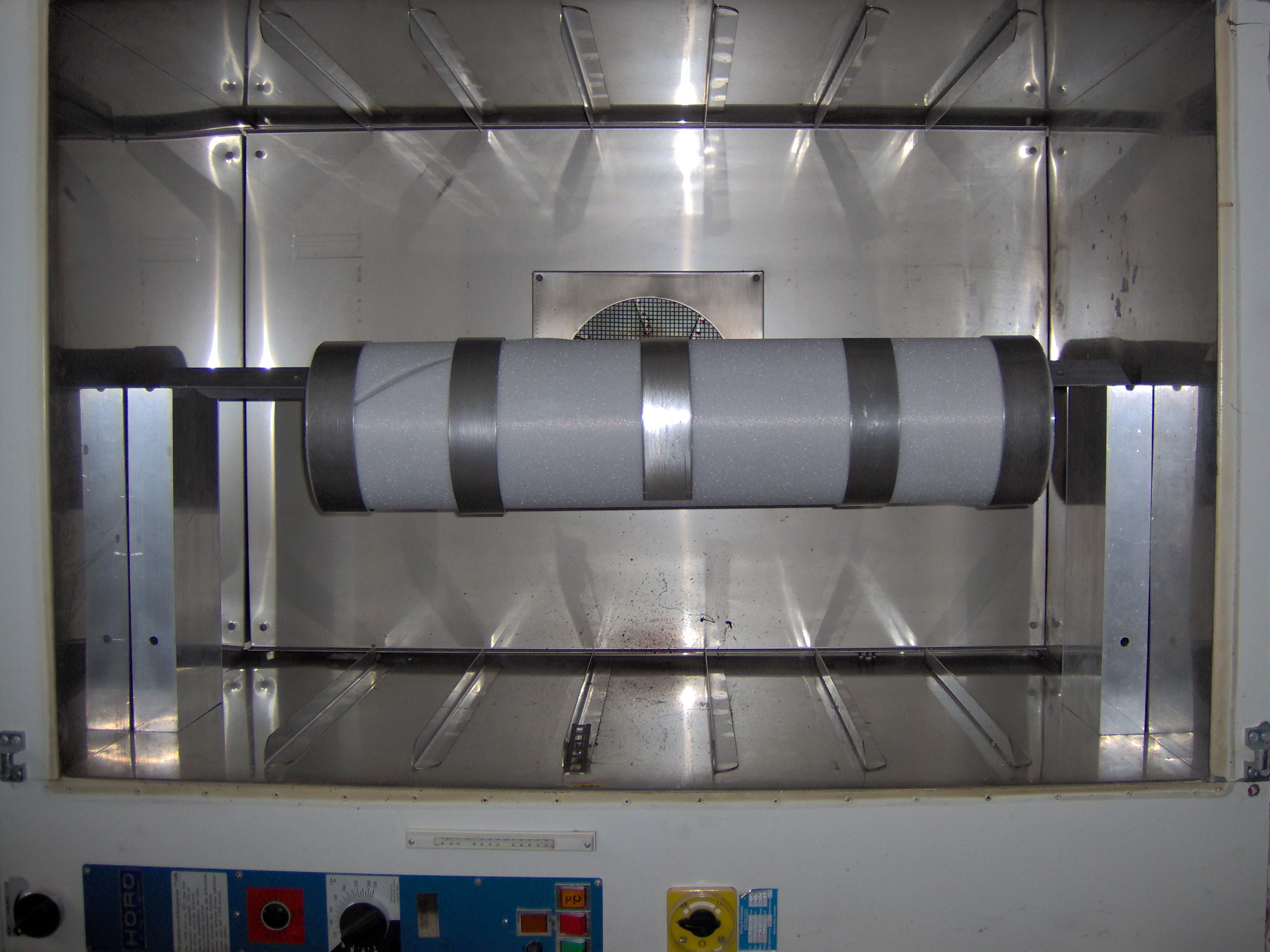
4.
|
Inside the oven
|
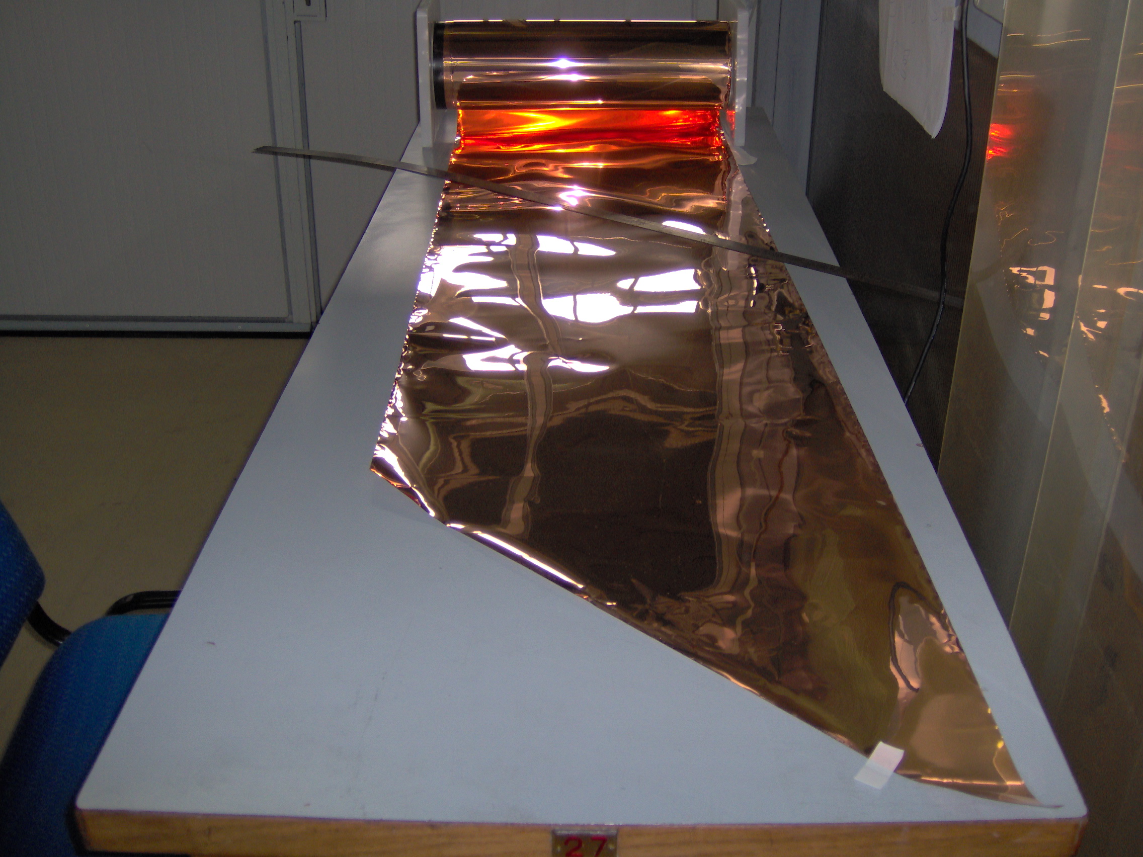
5.
|
Cu+kapton
|
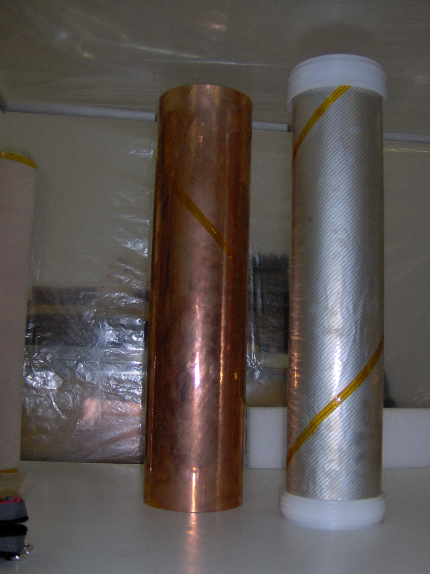
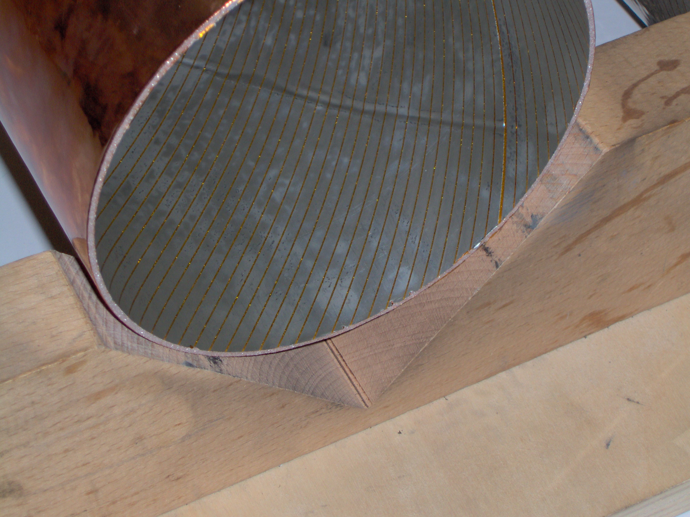
6.
|
A pair of cathods (inner and
outer)
|
7.
|
Detail of outer cathod
|
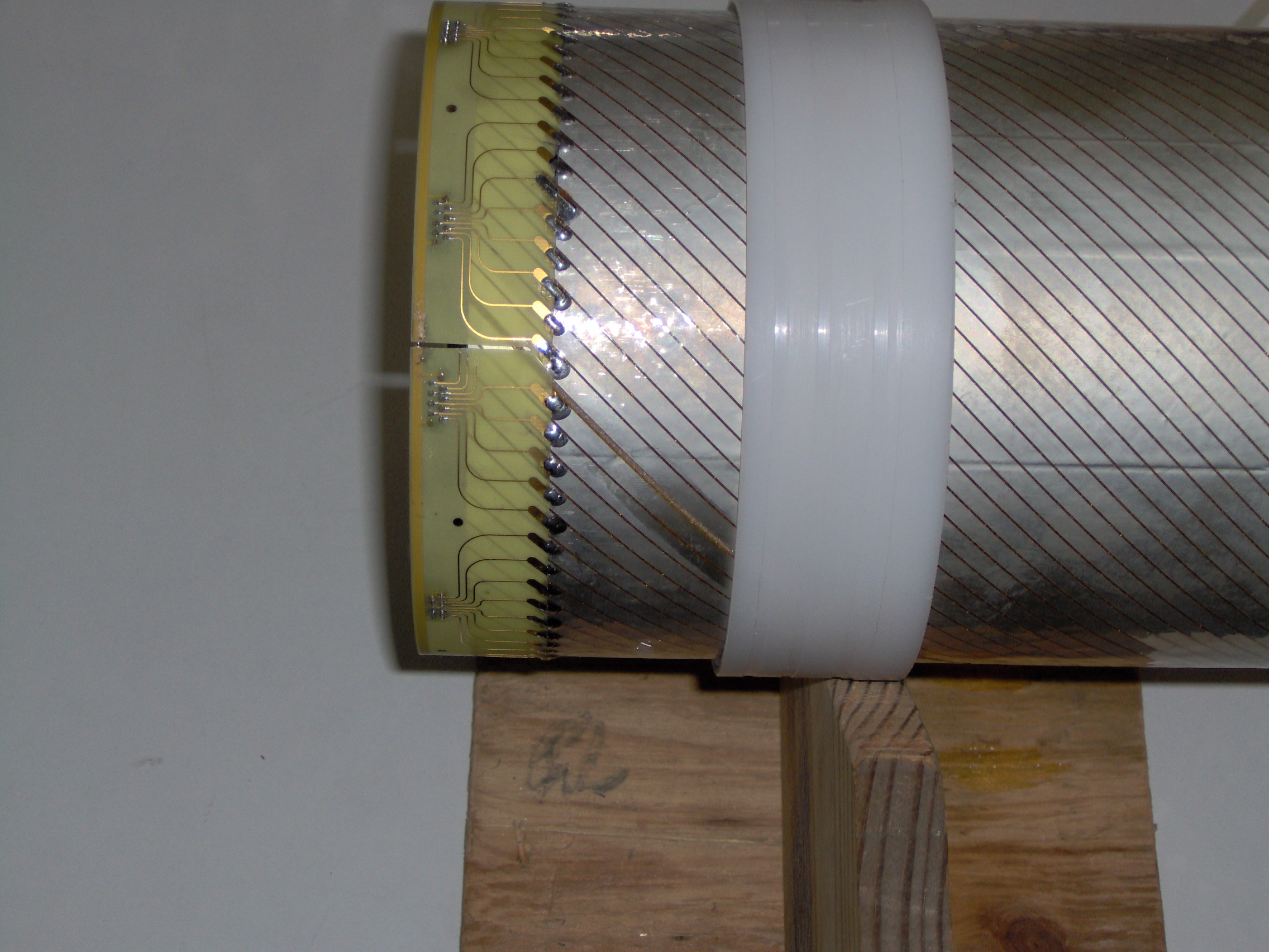
8.
|
Inner cathod: strip PCB
solderings
|
9.
|
Inner cathod: layout
|
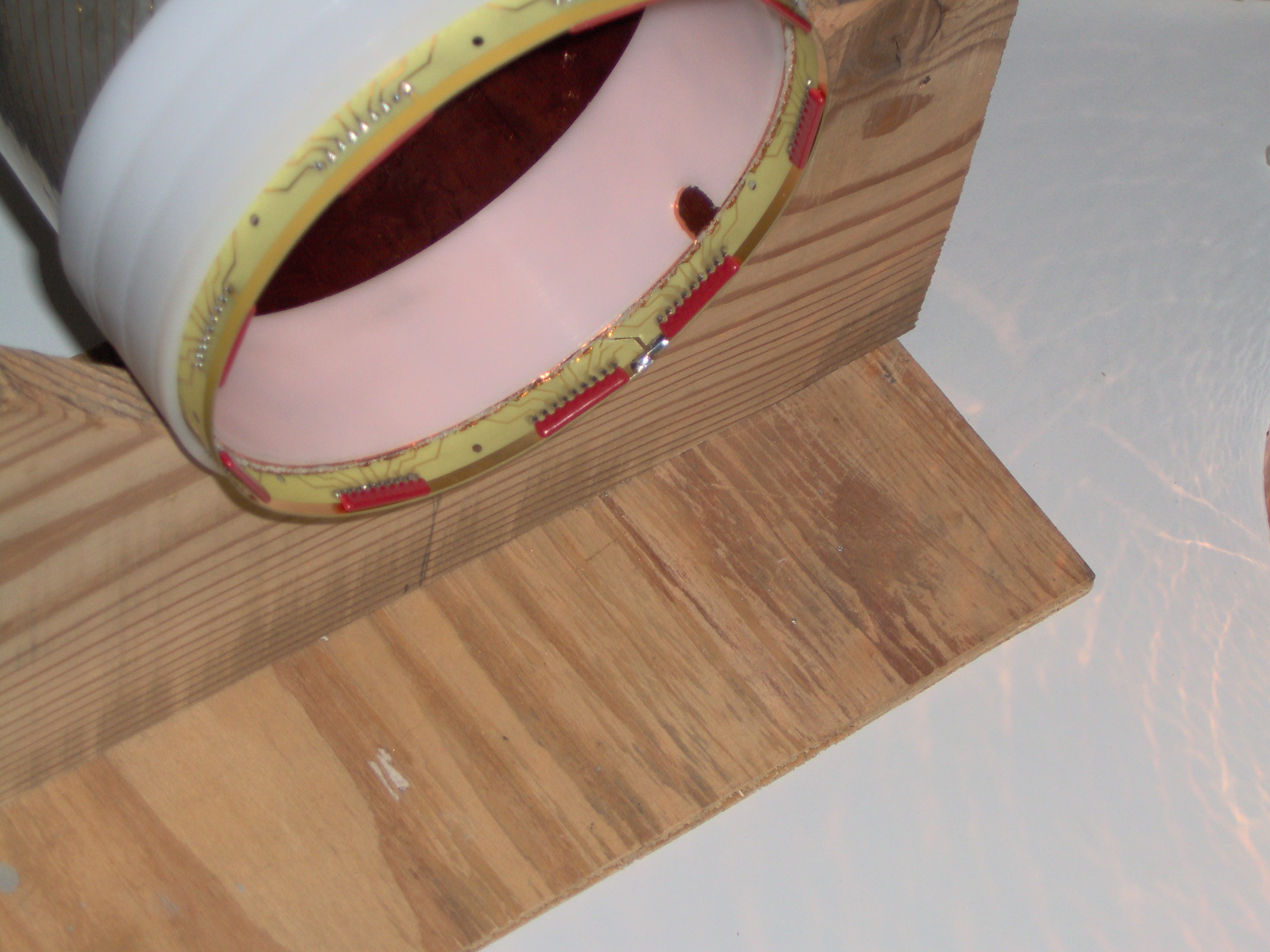
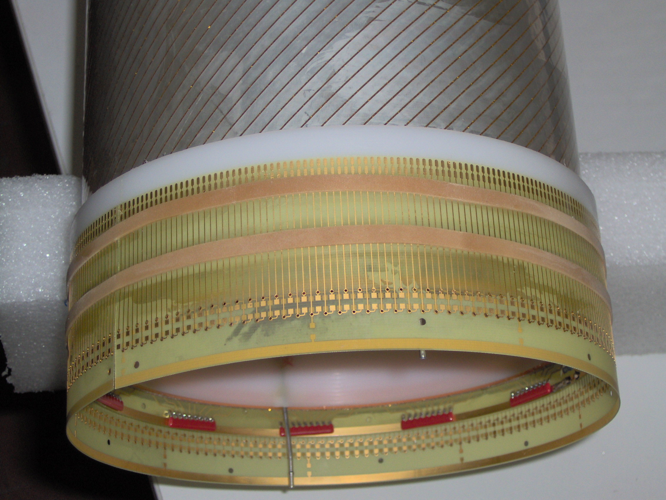
10.
|
Inner cathod: completed,
resistor side.
|
11.
|
Inner cathod: layout, completed
|
12.
|
Inner cathod: wire PCB glued
|
13.
|
Inner cathod: layout
|
14.
|
Soldering table
|
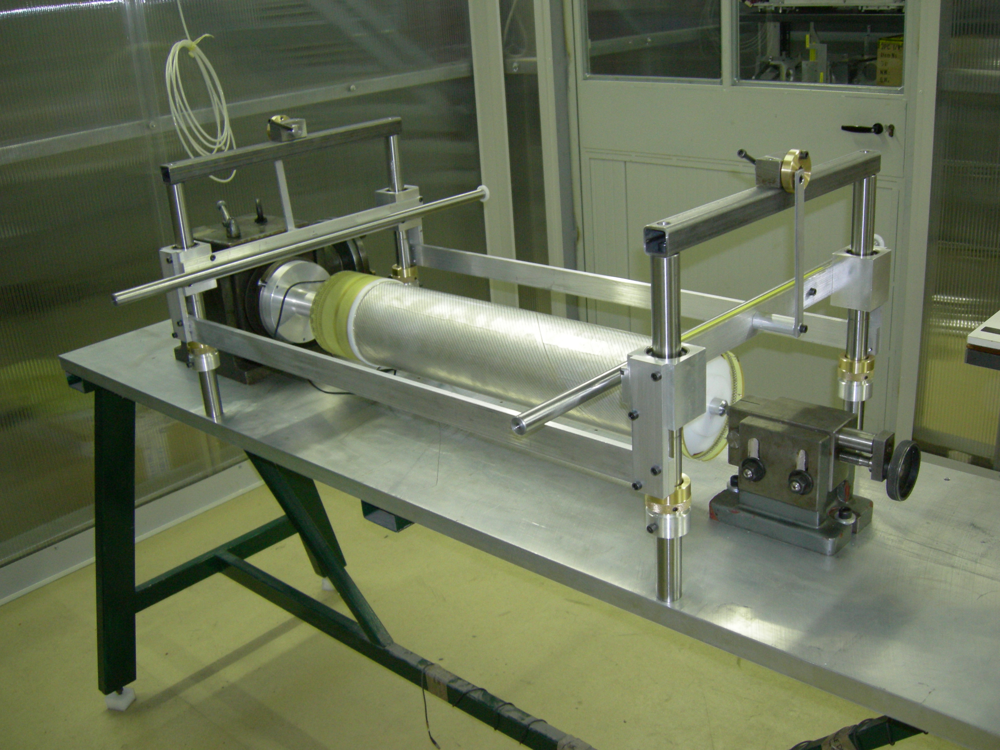
15.
|
Soldering table with inner
cathode (1)
|
16.
|
Soldering table with inner
cathode (2)
|
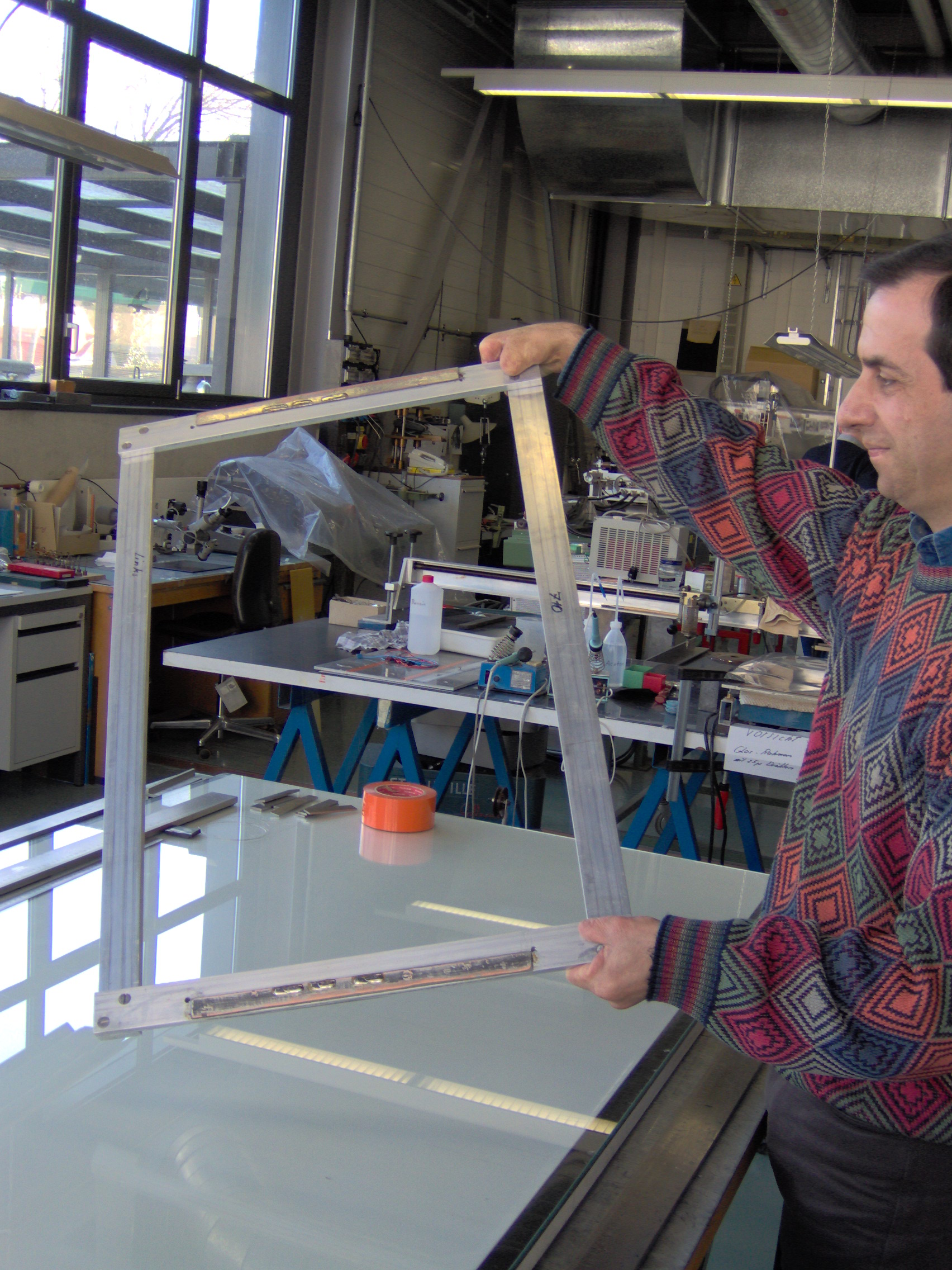
17.
|
movable frame with wires from
P.S.I.
|
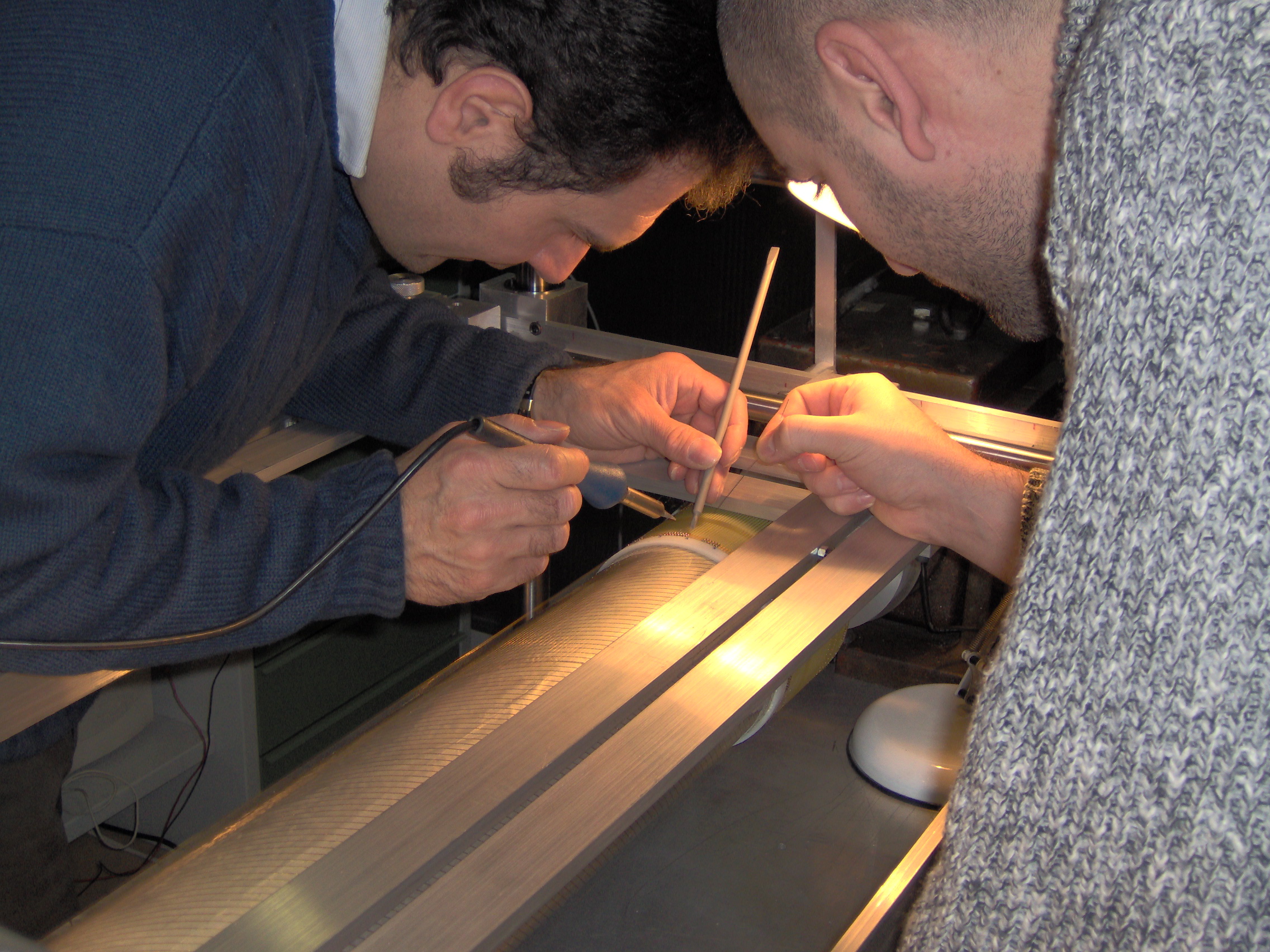
18.
|
Men at work (1)
|
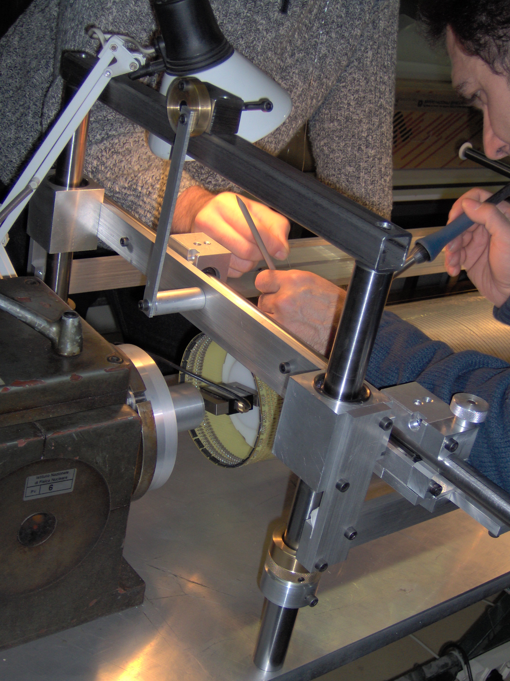
19.
|
| Men at work (2) |
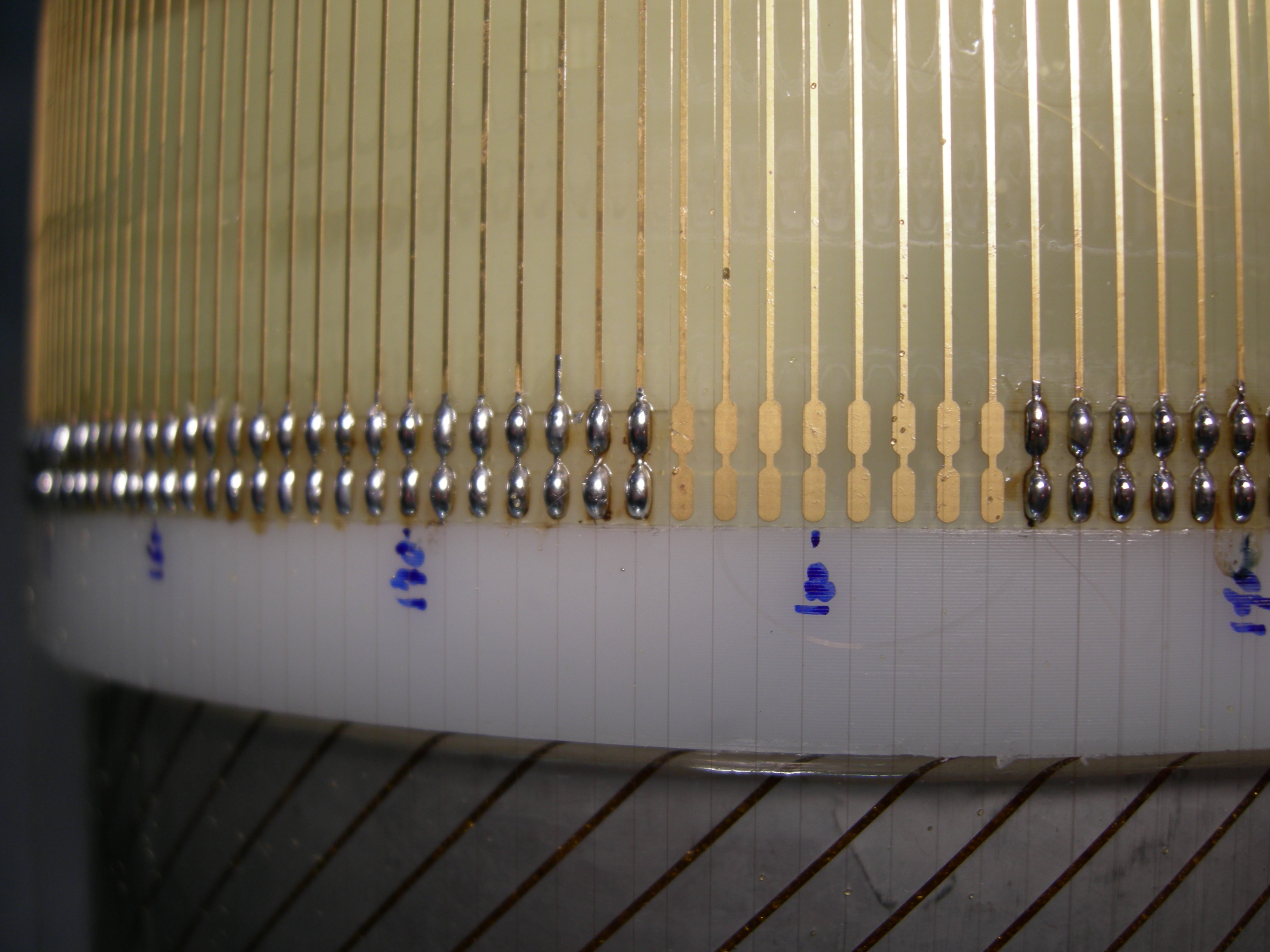
20.
|
Wire array, detail of soldering
|
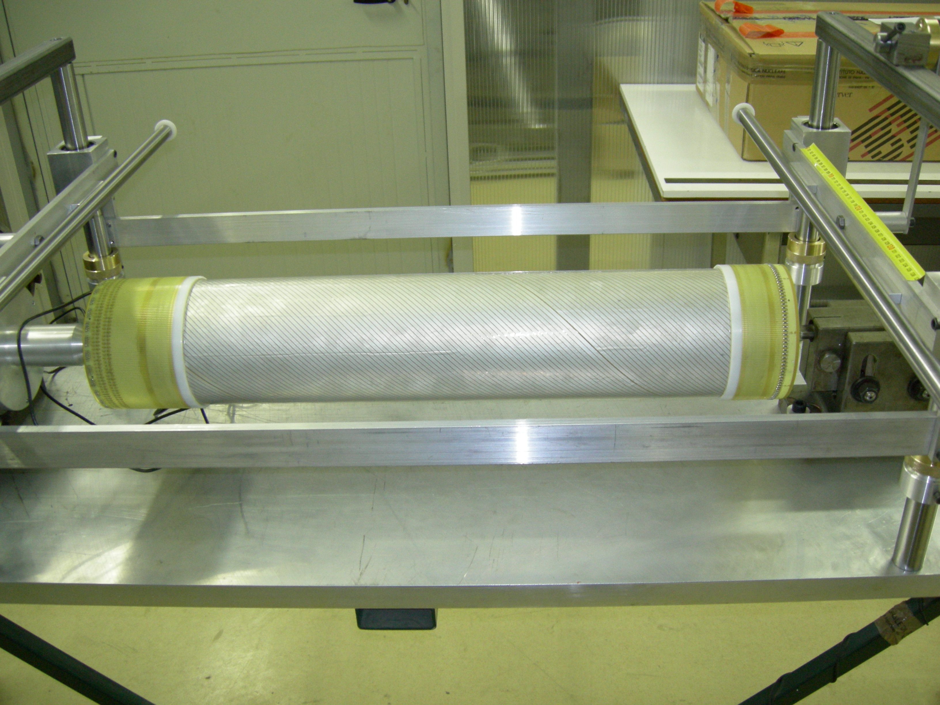
21.
|
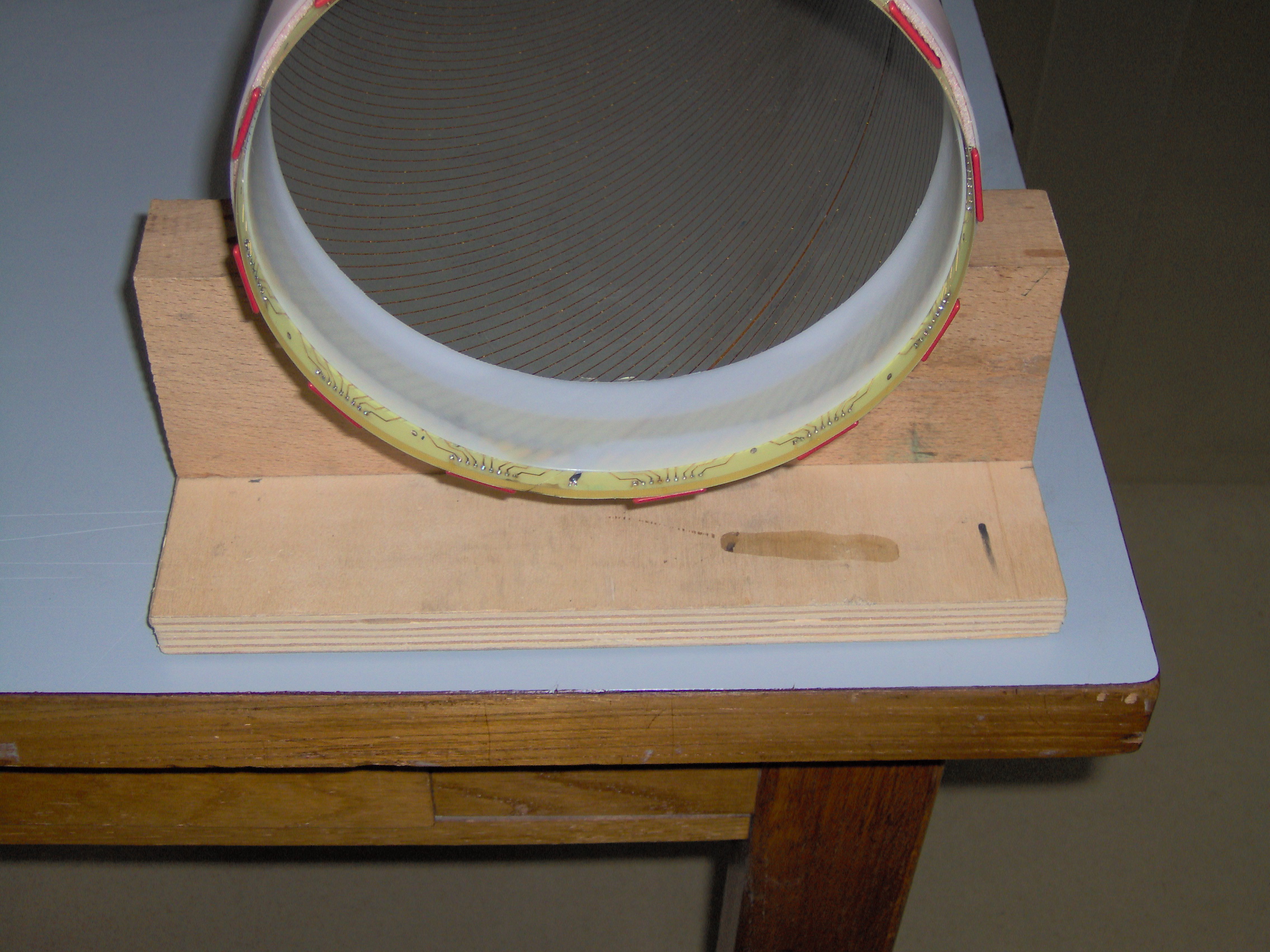
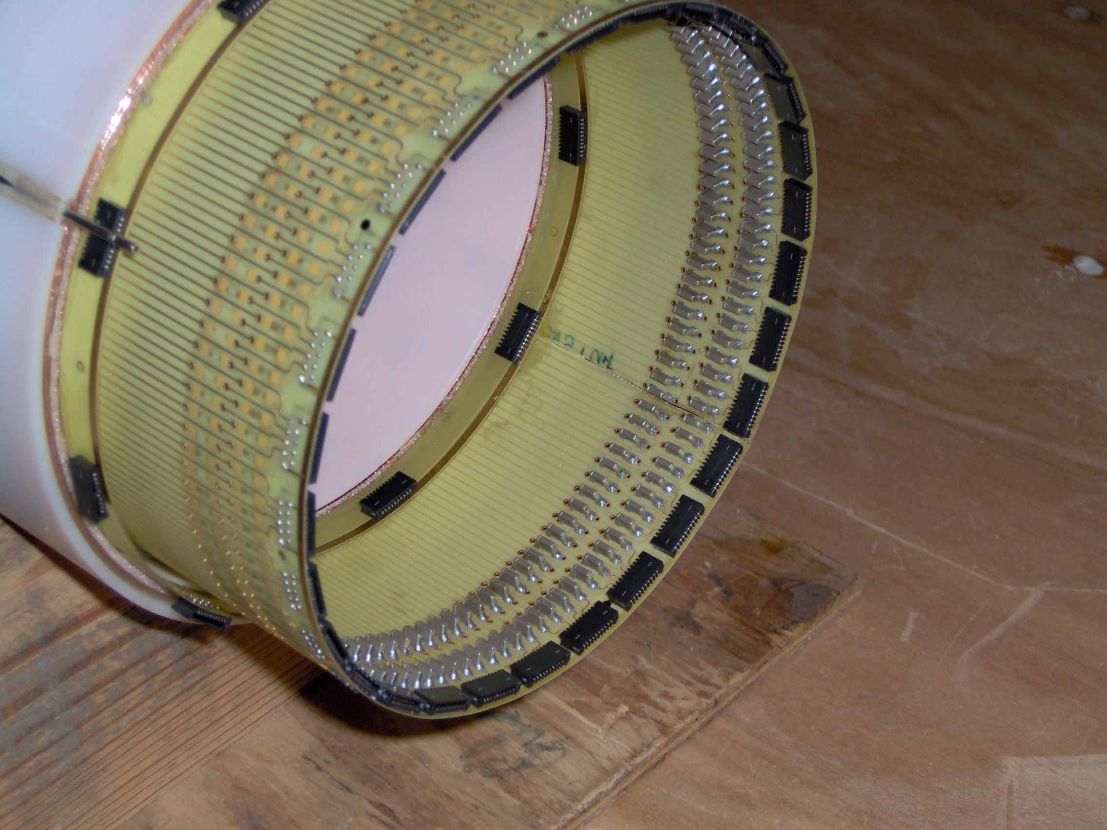
Inner cathode ready
|
22.
|
The outer cathode, detail
|
23.
|
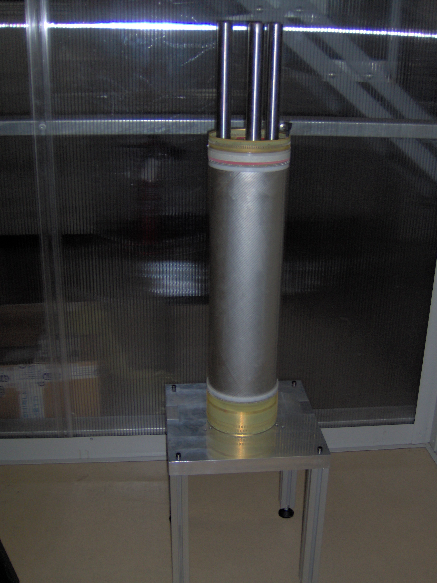
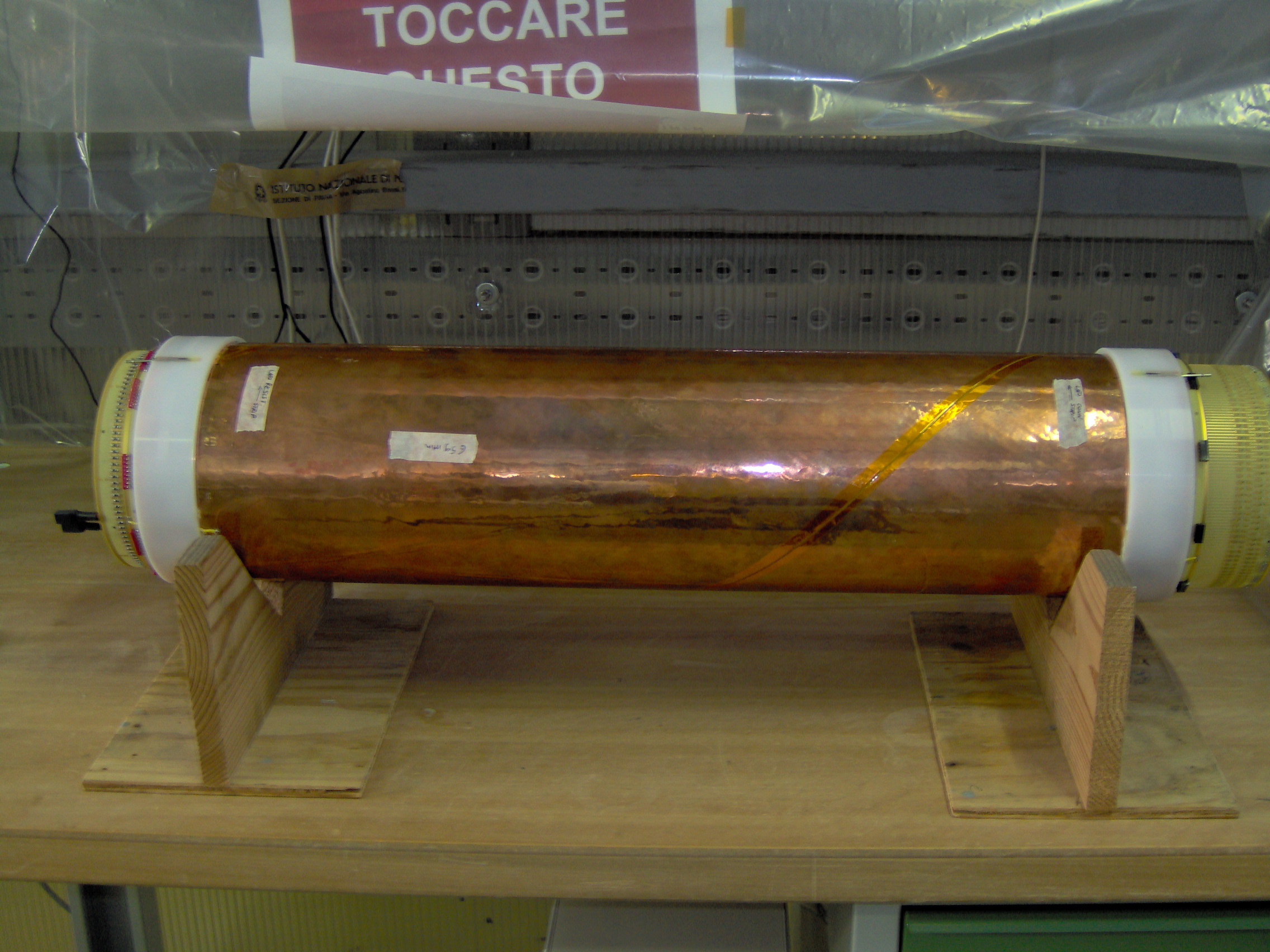
The chamber assembled (1)
|
24.
|
The chamber assembled (2),
resistor side, detail
|
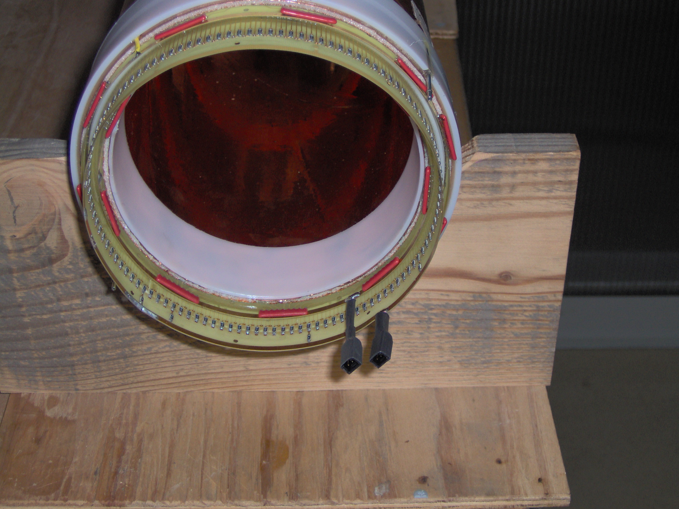
25.
|
| The chamber assembled (3),capacitor and connector side, detail |
26.
|
The chamber #1 assembled (4), layout
|
27.
|
| The chamber #1 and #2 assembled, layout |
28.
|
| Parameters, pdf table |
29.
|
Reference system for a chamber, layout
|
30.
|
Reference system for a chamber, planar layout
|
31.
|
HV module manual: Iseg 224M
|
32.
|
Gas system layout
|
33.
|
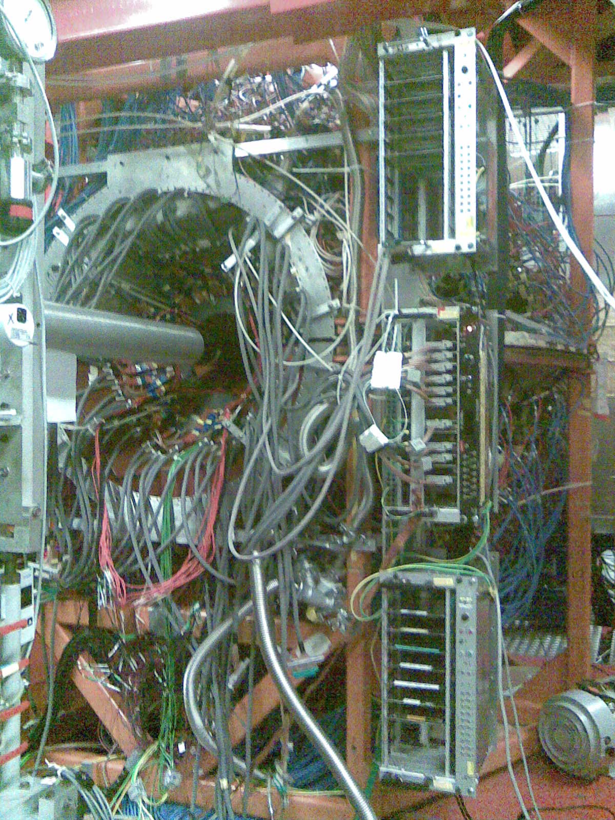
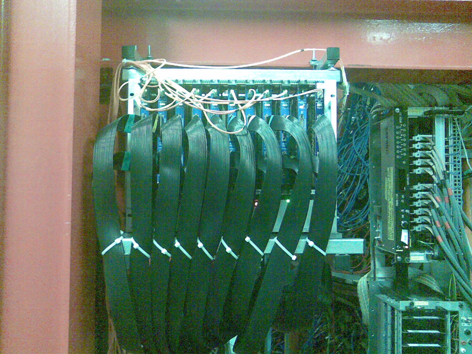
Installation Right side
|
34.
|
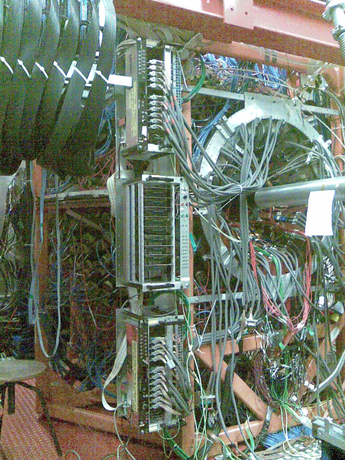
Installation Left side
|
35.
|
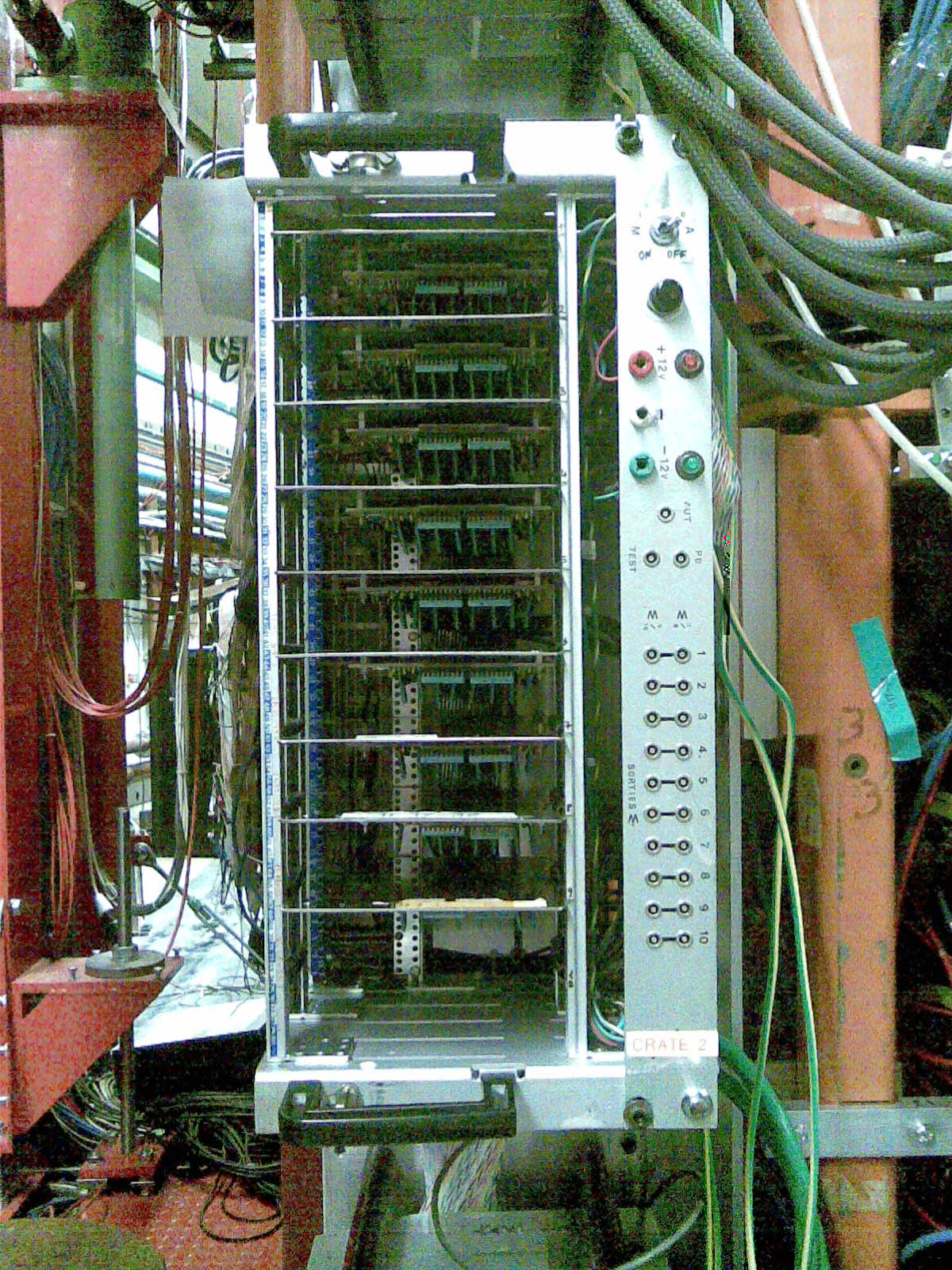
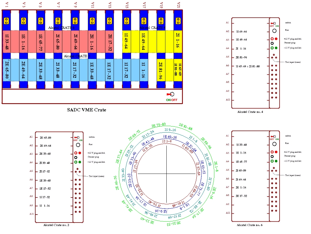
Alcatel Crate (Strips)
|
36.
|
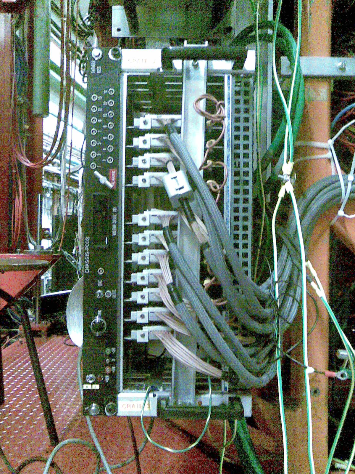
PCOS Crate (Wires)
|
37.
|
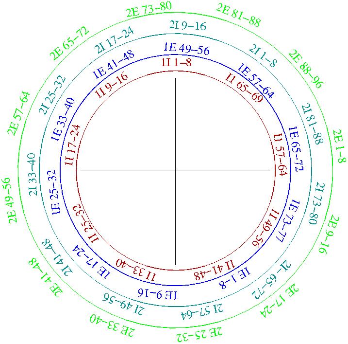
Strip connectors disposition
|
38.
|
SADC Crate
|
39.
|
Electronics full set up (layout)
|
40.
|